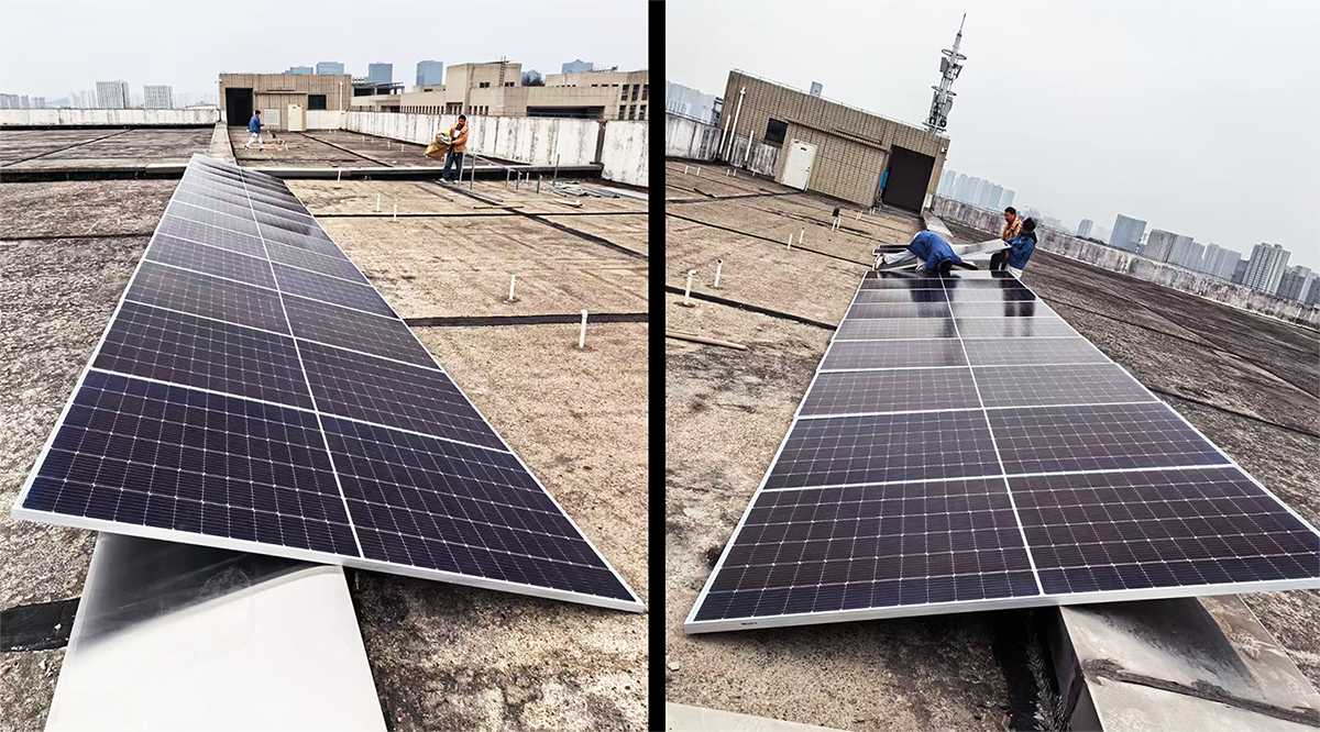
To continuously provide customers with a stable and reliable solar water pump operating experience, our company has set up dedicated solar panels in our factory to conduct rigorous on-site testing of the latest solar water pump control program. Through the efforts of our engineering team, a comprehensive program optimization and upgrade has been completed, now our performance can compete against products from well-known industry peers. The core upgrade highlights are as follows:
I. Comprehensive Optimization of Control Algorithm
Increased search time interval, reduced step size, and improved KI parameters.
Completed 600/700 full-condition real site testing verification.
Significantly reduced bus voltage fluctuations, greatly improving system operational stability.
II. Specific Improvements for Weak-Light situation
Addressing the issue of repeated undervoltage issues caused by insufficient sunlight in the early morning and late evening:
Default undervoltage recovery after 3 minutes.
Five consecutive undervoltage readings are considered low light, automatically extending the fault recovery delay.
All key parameters support custom settings.
After sunlight recovery, the fault count is automatically reset to zero, avoiding false shutdowns.
This upgrade effectively solves voltage fluctuations and repeated start-stop cycles in low light conditions in the early morning and late evening, making the system more adaptable to complex lighting environments and operating more smoothly and efficiently.
Welcome to upgrade to the latest version of our solar water pump control program! We always adhere to the principle of leaving all problems in the factory and bringing stability and efficiency to our customers. We will continue to optimize the program to provide you with even better solar water pump products and services.

1. Photovoltaic working principle
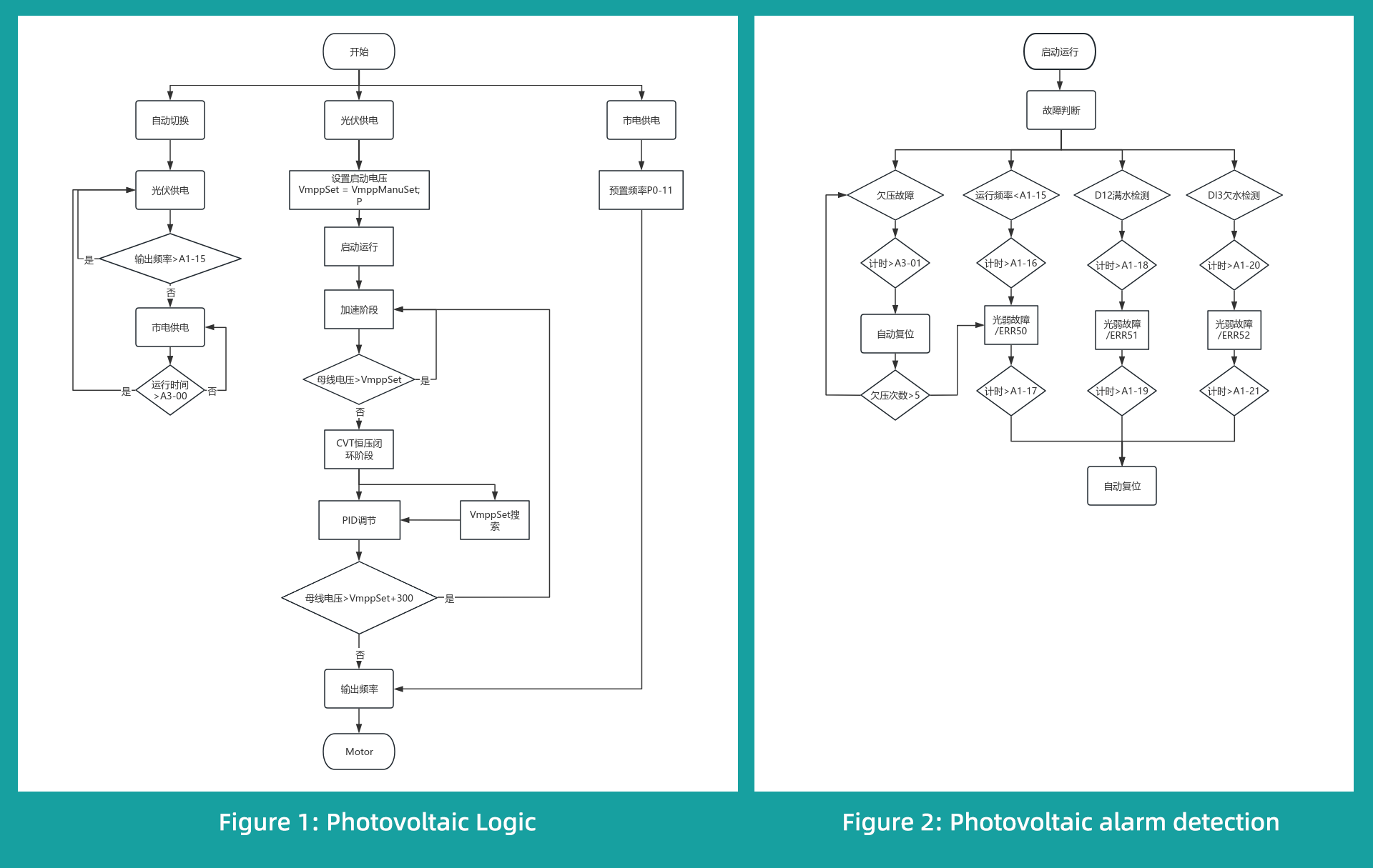
The photovoltaic function of a frequency converter adjusts the inverter output by changing the power of the photovoltaic panels. Its logic principle is shown in the diagram below.
2. Parameter settings
Set motor parameters:P4-00~P4-06.
Terminal settings : DI1 terminal P5-00=01 (forward operation), DI2 terminal P5-01=41 (full water tank detection valid), DI3 terminal P5-02=42 (low water well detection valid), DI4 terminal P5-03=43 (manual power supply mode switching valid), P6-00=31 (water pump control valve).
Photovoltaic module settings : A1-00=1 (Photovoltaic enable is effective), A1-03=Open circuit voltage (currently, we manually input the open circuit voltage according to the photovoltaic panel nameplate), A1-02=Starting voltage (this value is generally set to about 80% of the open circuit voltage), A1-04=1 (Photovoltaic power supply mode).
Automatic operation settings : P7-41=0 (no protection when starting the terminal), P9-17=1 (automatic recovery from undervoltage fault)
3. Functional Testing
(1) Photovoltaic panel testing
Test conditions:
Photovoltaic panels: (550W*48.9V)*13 (The photovoltaic panels are shaded, and the maximum output power of the motor is around 2kW)
Frequency converter: 7.5kW asynchronous frequency converter
Motor: 3KW asynchronous submersible pump
Test parameters:
for A1-02=540V (start-up voltage), A1-05=2s (tracking interval), A1-06=5V (hysteresis voltage), A1-07=2V (step size), A1-10=1.0, A1-11=3.0, A1-12=1.0, A1-13=3.0
(Improving stability and fault response mechanisms)
Compared to before, we increased the search interval and decreased the step size, and increased the KI value. Besides testing at 600, we also tested at 700. Bus voltage fluctuations decreased, significantly improving stability.
To address the issue of repeated undervoltage caused by insufficient light in the morning and evening, we defaulted to a 3-minute undervoltage recovery period. If five consecutive undervoltage occurrences occur, it's considered weak light, and a longer delay is applied for fault recovery. All parameters are configurable. Furthermore, during this process, the count is reset to zero when light returns. ( Testing VECHI、INVT、GTAKE,SIMPHOENIX undervoltage fault, with a default 3-minute delay for repeated occurrences .)
| Test parameters | Test log for the entire day from March 11th to March 12th, 2026 | Results Analysis |
|---|
| Output speed | 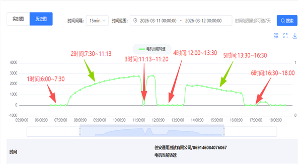
| Overall trend: Output power increases in the morning and decreases in the afternoon, with generally stable operation. Specific analysis: 1. Time: Insufficient sunlight in the morning; 2. Time: Normal operation in the morning; 3. Time: One instance of low voltage; 4. Time: Stopped operation during lunch break; 5. Time: Normal operation in the afternoon; 6. Time: Insufficient sunlight in the evening. Question: The low voltage occurred at time 3; it is uncertain whether it was caused by cloud cover or MPPT reverse search. |
| Fault Log | 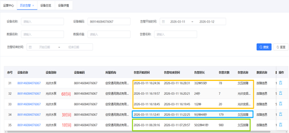
| Time 1 is the alarm for insufficient light in the morning; Time 3 is the alarm for a single undervoltage event; Time 6 is the alarm for insufficient light in the evening. |
| Bus voltage | 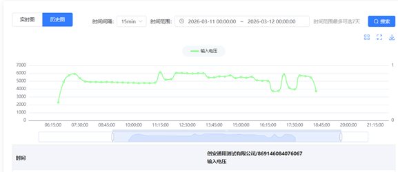
| The busvoltage fluctuates little during normal operation. |
| Output speed | 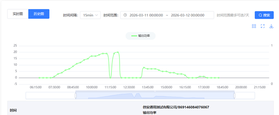
| The output speed is consistent with the output power. |
(2) Photovoltaic simulated power supply test
| Power | Parameter settings | Waveform | Data Records | Results Analysis |
|---|
| 620V/4A/1.7KW | A1-02=540 A1-05=2s A1-06=5V A1-07=2V A1-10=1.0 A1-11=3.0 A1-12=1.0 A1-13=3. | 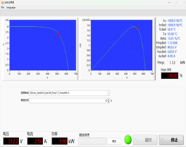
| 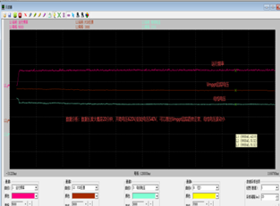
| The test lasted approximately 20 minutes, the tracking direction was correct, and the bus fluctuation was minimal. Although small-step tracking is slower, with a reasonable starting voltage, this has little impact. |
| 620V/4A/1.7KW | VECHI、INVT、GTAKE,SIMPHOENIX S123/380V | 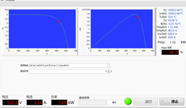
| VECHI、INVT、GTAKE,SIMPHOENIX the test results were similar. |
|
(3) Fault and terminal testing
| Function | Phenomenon
| Test Results |
|---|
| Low light alarm / ERR50 | 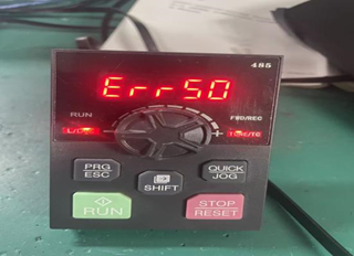
| Set PA-15=10HZ, A1-16=10S, A1-17=10, operating frequency 20HZ, ERR50 error is reported after a 10s delay, and the fault is restored after a 10s delay. |
| Full water alarm /ERR51 | 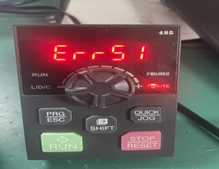
| Set P5-01=41, short-circuit DI2 and COM, A1-18=10S, A1-19=10S. After startup, an error ERR51 is reported after a 10-second delay. Disconnect DI2 and COM, and the fault is restored after a 10-second delay. |
| Low water alarm / ERR52 | 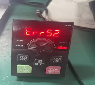
| Set P5-01=43, short-circuit DI3 and COM, A1-20=10S, A1-21=10S. After startup, an error ERR52 is reported after a 10-second delay. Disconnect DI3 and COM, and the fault is restored after a 10-second delay. |
| Morning and evening light cannot provide sufficient illumination for repeated undervoltage processing | DC power supply, set A1-16=20S, A3-01=5S, B2-05=250V, A1-02>bus voltage, start operation. | Decreasing the voltage triggers an undervoltage fault; Increasing the voltage and delaying for 5 seconds to recover from the fault, after 5 such occurrences, triggers an ERR50 fault, which is then resolved with a 20-second delay. |
| Automatic switching function between photovoltaic and grid in automatic mode | 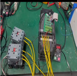
| Setting A1-04=0 (automatic switching mode) and P6-00=31 (switching relay) defaults to photovoltaic panel priority power supply. When TA1/TB1 is turned on, the power supply switches to the photovoltaic panel. After the bus voltage is stable and the starting conditions are met, operation is allowed. When the light is insufficient, the inverter determines that the light is weak based on its own weak light conditions. The inverter automatically stops and TA1/TB1 is turned off. TA1/TC1 is turned on to switch to grid power supply and automatically runs. After the running time reaches A2-00 time, it automatically stops and switches to photovoltaic panel power supply. This logic is used to determine the switching operation in a loop. |


 Address: Building 1#, Auto Science and Technology Park, No. 13, Huanlian Road, Changsha High-tech Development Zone, Hunan Province
 ") +86 - 19924552818 (Whatsapp)
+86 - 19924552818 (Whatsapp)