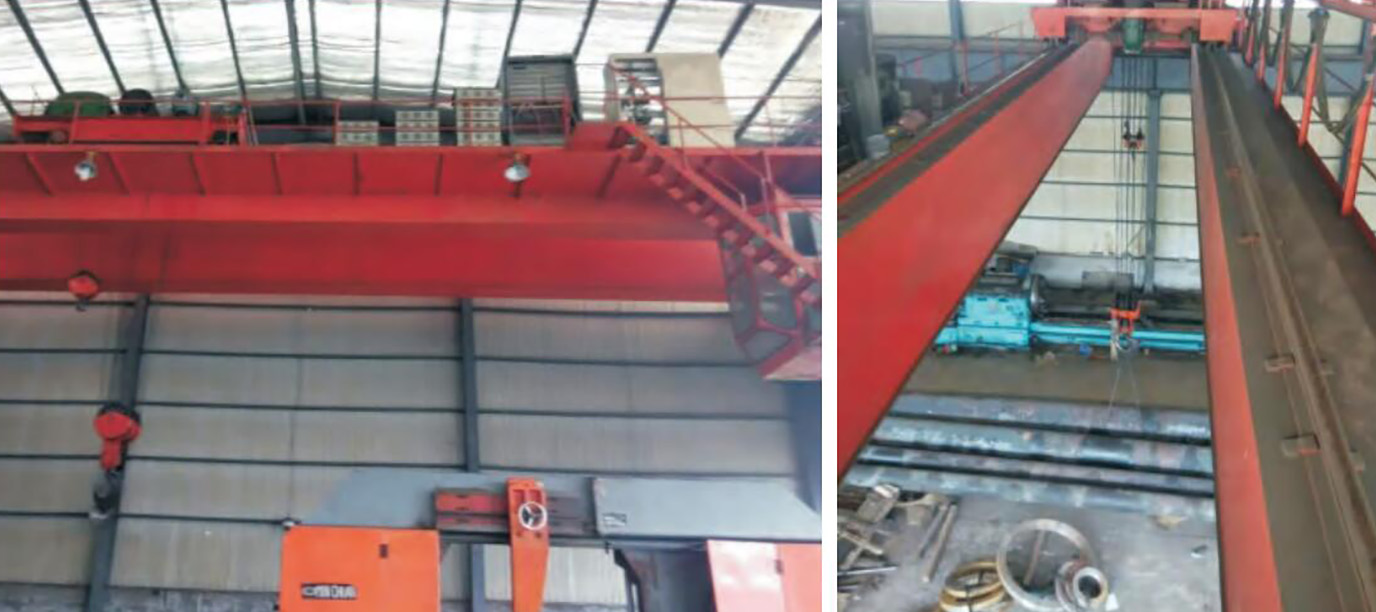
Overview
Bridge crane, commonly known as "driving", is a kind of lifting machinery widely used in industrial and mining enterprises, its operating mechanism is composed of three basically independent driving systems: car driving system, hook driving system, and walking system. The KD600 inverter has successfully reformed these three systems, mainly describing the transformation process of the walking system.
Scheme Advantages
Field oriented current open-loop vector control, fully decoupled motor variables, large low-frequency torque, fast response, etc;
KD600 adopts PG free open-loop vector control mode and vectorized V/F mode, and amplifies the power level configuration of the first gear;
Frequency range: 0.5-600Hz segment setting, stepless continuous adjustment;
Working voltage range: 380V ± 20%, and the bus voltage drops to 360VDC instantly for trouble free operation;
Overload capacity: 150% of rated current, 1 minute allowed; 200% rated current, 1s allowed;
Torque characteristics: starting torque, greater than 2 times of rated torque; Low frequency torque, greater than 1.6 times of rated torque at 1Hz; The braking torque is greater than the rated torque.
Operating Characteristics
The crane lifting mechanism has a large starting torque, which usually exceeds 150% of the rated torque. If overload and other factors are considered, at least 200% of the rated torque shall be provided during the starting and accelerating process;
When the lifting mechanism runs downward, the motor will be in regenerative power generation state and must be energy consumption braking or regenerative feedback to the grid;
The load of the lifting mechanism changes dramatically when the lifted object leaves or touches the ground, and the frequency converter shall be able to control the impact load smoothly;
As the traveling speed of the front and rear traveling mechanism of the crane is not high during the mechanical design, the converter can be used for proper overspeed to improve the working efficiency.
Simple Wiring Diagram

Parameter Setting and Description (left and right motor traveling parameters)
| Parameter | Explain | Parameter setting | Explain |
|---|---|---|---|
| P0-00=0 | VF control | P5-00=1 | Forward |
| P0-04=1 | External terminal start stop | P5-01=2 | Carry out later |
| P0-06=1 | Digital frequency setting | P6-00=2 | Relay 1 fault output |
| P0-14=60.00 | Maximum frequency | P4-01=1.6KW | Connected motor power |
| P0-16=60.00 | Upper limit frequency | P4-02=380V | Motor rated voltage |
| P0-11=60.00 | Digital setting frequency | P4-04=3.3A | Motor rated current |
| P0-23=3.0s | Acceleration time | P4-05=50Hz | Rated frequency of motor |
| P0-24=2.0s | Deceleration time | P4-06=960R/Min | Rated speed of motor |
Note: When one frequency converter is used with two motors, it is strongly recommended to install a matching thermal relay at the front end of each motor to protect each motor.
Operation Effect Analysis
The soft start and soft stop during startup are realized, which reduces the impact on the power grid;
After using the frequency converter, the original shift contactor and speed regulating resistor are omitted, which not only saves the maintenance cost, but also reduces the downtime for maintenance, thus increasing the output;
When the main hook works at 5Hz~30Hz, the energy saving effect is very obvious;
The frequency converter is used to control the front and rear traveling, and the left and right traveling mechanism series can realize the over frequency work. Under the premise of ensuring safety, the work efficiency is greatly improved, and the maintenance workload of the traveling equipment due to frequent replacement of AC contactors is also reduced.
Closing Remarks
The frequency converter is used to control the front and back walking and the left and right walking mechanism series, which can realize overclocking work, greatly improve the work efficiency under the premise of ensuring safety, and also reduce the maintenance workload of driving equipment due to frequent replacement of AC contactors.


 Address: Building 1#, Auto Science and Technology Park, No. 13, Huanlian Road, Changsha High-tech Development Zone, Hunan Province
  +86 - 19924552818 (Whatsapp)


